NEET 2025 Physics Full Wave Rectifier Operation MCQ Question
A full wave rectifier circuit with diodes (D₁) and (D₂) is shown in the figure. If input supply voltage Vₙ = 220sin(100πt) volt, then at t = 15 msec
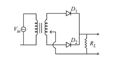
D₁ is forward biased, D₂ is reverse biased
D₁ is reverse biased, D₂ is forward biased
D₁ and D₂ both are forward biased
D₁ and D₂ both are reverse biased
Correct Answer
Detailed Explanation
To determine the state of the diodes (D₁ and D₂) at time t = 15 ms, we first need to calculate the input voltage at that time. The input supply voltage is given by the equation:
Substituting t = 15 ms (or 0.015 s):
Calculating , we find it is approximately 0.999. Therefore:
In a full wave rectifier circuit, D₁ conducts when the input voltage is positive, and D₂ conducts when the input voltage is negative. Since at t = 15 ms, the voltage is positive (approximately 219.78 volts), D₁ is forward biased and D₂ is reverse biased. Thus, the correct answer is A.
For options B, C, and D:
- B is incorrect because it states D₁ is reverse biased, which contradicts our calculation.
- C is incorrect as it suggests both diodes are forward biased, which is not possible at the same time in a full wave rectifier.
- D is incorrect as it states both are reverse biased, which is also not possible given the positive voltage at this time.
Found an issue with this question?
Related Questions
More from 2025
In bryophytes, the gemmae help in which one of the following?
The plates of a parallel plate capacitor are separated by d. Two slabs of different dielectric constant K₁ and K₂ with thickness 3d/8 and d/2, respect...
Energy and radius of first Bohr orbit of He⁺ and Li²⁺ are [Given Rₕ = 2.18 × 10⁻¹⁸ J, a₀ = 52.9 pm]