

AIPMT MAINS2010Physics-Digital Electronics
AIPMT MAINS 2010 Physics Logic Gates MCQ Question
Type: MCQ-conceptual-Medium-Class 12
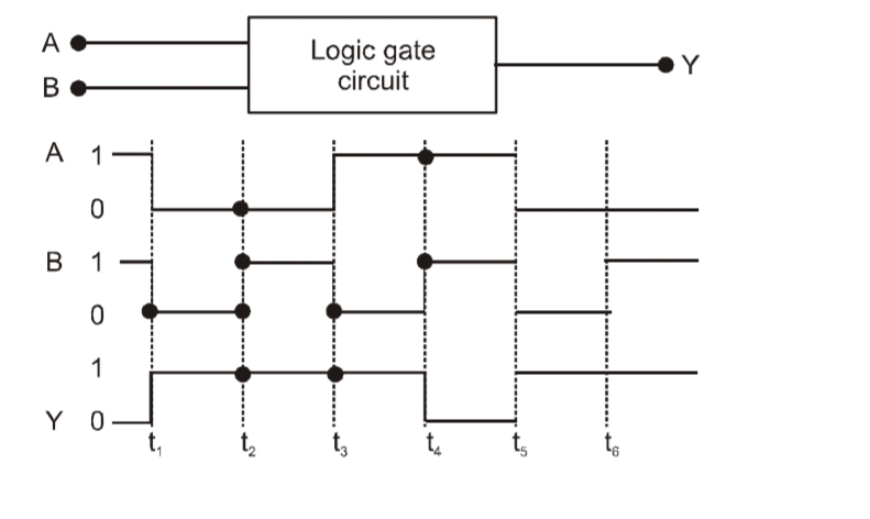
The following figure shows a logic gate circuit with two inputs A and B and the output Y. The voltage waveforms of A, B and Y are as given. The logic gate is
A
NOR gate
B
OR gate
C
AND gate
D
NAND gate
Correct Answer
Option D
Detailed Explanation
The truth table for the given waveforms matches that of a NAND gate, where the output is 0 only when both inputs are 1.
Found an issue with this question?