
MarksRiser
MarksRiser
AIPMT PRELIMS2007Physics-Digital Electronics

AIPMT PRELIMS 2007 Physics Logic Gates MCQ Question

Type: MCQ-conceptual-Medium-Class 12

In the following circuit, the output Y for all possible inputs A and B is expressed by the truth table
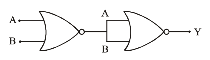
Question diagram
A

ABY001011101110\begin{array}{ccc} \text{A} & \text{B} & \text{Y} \\ 0 & 0 & 1 \\ 0 & 1 & 1 \\ 1 & 0 & 1 \\ 1 & 1 & 0 \end{array}

B

ABY001010100110\begin{array}{ccc} \text{A} & \text{B} & \text{Y} \\ 0 & 0 & 1 \\ 0 & 1 & 0 \\ 1 & 0 & 0 \\ 1 & 1 & 0 \end{array}

C

ABY000011101111\begin{array}{ccc} \text{A} & \text{B} & \text{Y} \\ 0 & 0 & 0 \\ 0 & 1 & 1 \\ 1 & 0 & 1 \\ 1 & 1 & 1 \end{array}

D

ABY000010100111\begin{array}{ccc} \text{A} & \text{B} & \text{Y} \\ 0 & 0 & 0 \\ 0 & 1 & 0 \\ 1 & 0 & 0 \\ 1 & 1 & 1 \end{array}

Correct Answer

Option D

Detailed Explanation

The circuit represents a logic gate configuration that matches the truth table in option D.

Found an issue with this question?